





































WEL2 & WEL6
Features
Heat exchangers of the WEL2000 range (shown: WEL2001/A040) are used to cool process/barrier fluids in seal supply circuits. The heat exchangers are made of helical, laser-welded finned tubes. The cooling medium is ambient air. There is a choice of three different basic versions of the WEL2000 range, supplied fully assembled along with valves, base frame and other system components.
Circulation in accordance with API 682 / ISO 21049: Plan 21, Plan 22, Plan 23, Plan 41
Advantages
- Helical finned tube design with vertical arrangement of the fins to the wind direction: the solution for high cooling capacities
- Welded finned tubes without gaps for guaranteed optimum energy transmission
- Universal usage: high-quality 1.4571 stainless steel finned tube design
- No cooling water connection or heating required for the cooling water pipe in winter
Standards and approvals
- PED 2014/68/EU (Design and production in accordance with EU Pressure Equipment Directive)
- ASME VIII, Div. 1 (Calculation)
Recommended applications
- Chemical industry
- Petrochemical industry
- Oil and gas industry
- Refining technology
- Power plant technology
Notes
WEL heat exchangers should be installed in well ventilated places indoors or, ideally, outdoors. Vertical installation is essential.
Product variants
| **** | WEL2 - single | WEL2 - double | WEL2 - quadrupel | WEL6 - single | WEL6 - double | WEL6 - quadrupel |
|---|---|---|---|---|---|---|
| Cooler design | 1 finned tube, coiled | 2 finned tubes, coiled | 2x2 finned tubes, coiled | 1 finned tube, coiled | 2 finned tubes, coiled | 2x2 finned tubes, coiled |
| Conformity | API 682 | API 682 | API 682 | |||
| Design code | ASME VIII, Div. 1 oder PED2014/68/EU | ASME VIII, Div. 1 oder PED2014/68/EU | ASME VIII, Div. 1 oder PED2014/68/EU | ASME VIII, Div. 1 oder PED2014/68/EU | ASME VIII, Div. 1 oder PED2014/68/EU | ASME VIII, Div. 1 oder PED2014/68/EU |
| Weight (empty) | 17 kg | 34 kg | 75 kg | 20 kg | 36 kg | 63 kg |
| Process fluid | ||||||
| Process connections1) | G 1/2" (female) | G 1/2" (female) | G 1/2" (female) | Flansch 3/4", 600 lbs | Flansch 3/4", 600 lbs | Flansch 3/4", 600 lbs |
| Drain / vent connection1) | 1/2" NPT (female) | 1/2" NPT (female) | 1/2" NPT (female) | |||
| Design pressure1) | G 1/2" (female) | G 1/2" (female) | G 1/2" (female) | 1/2" NPT (female) | 1/2" NPT (female) | 1/2" NPT (female) |
| Design temperature1) | 110 bar (g) | 110 bar (g) | 110 bar (g) | 76 bar (g) | 76 bar (g) | 76 bar (g) |
| Material (metal parts)1) | 200 °C | 200 °C | 200 °C | 150 °C | 150 °C | 150 °C |
| 14.571 | 14.571 | 14.571 | 316/316L | 316/316L | 316/316L | |
| Cooling capacity depending on process fluid | ||||||
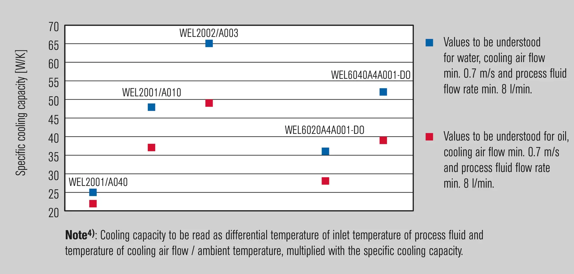
| Water | (low flow2) / high flow3)) | (low flow2) / high flow3)) | (low flow2) / high flow3)) | (low flow2) / high flow3)) | (low flow2) / high flow3)) | (low flow2) / high flow3)) |
| Oil ISO VG10 | 1,0 kW / 1,2 kW | 1,9 kW / 2,4 kW | 2,6 kW / 3,2 kW | 0,8 kW / 0,9 kW | 1,5 kW / 1,8 kW | 2,1 kW / 2,5 kW |
| 0,9 kW / 1,1 kW | 1,5 kW / 2,0 kW | 2,0 kW / 2,6 kW | 0,7 kW / 0,8 kW | 1,2 kW / 1,6 kW | 1,6 kW / 2,1 kW |
¹⁾ further versions available upon request (e.g. operating conditions, flange connection 1500 lbs, duplex material, etc.)
²) Low Flow: 8 l/min (process fluid), 0.7 m/s (Wind speed), ΔT = 40 K ( Tfluid - Tambient)
3) High Flow: 15 l/min (process fluid), 1.0 m/s (Wind speed), ΔT = 40 K ( Tfluid - Tambient)
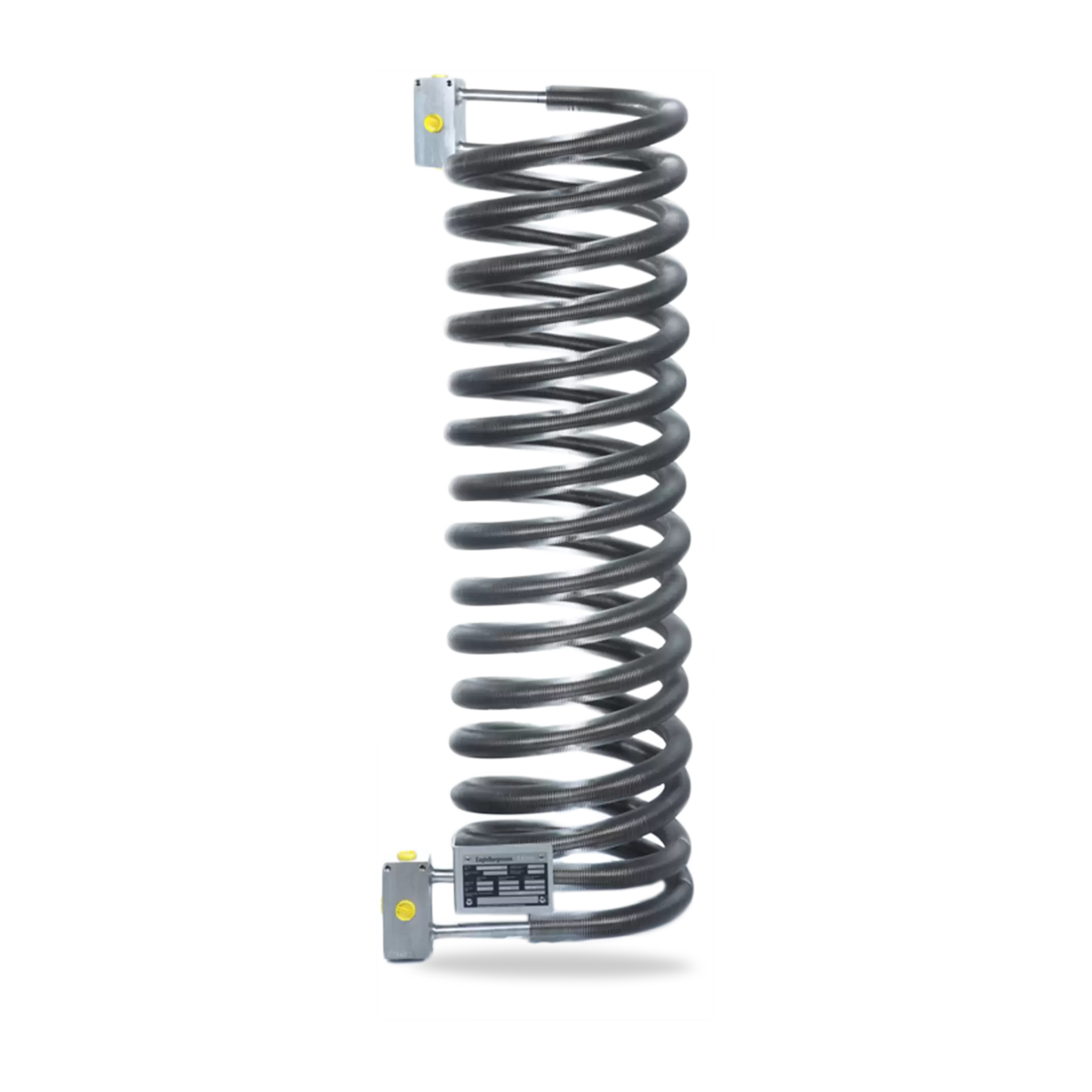
WEL2001/A010
Two finned tubes switched on parallel.
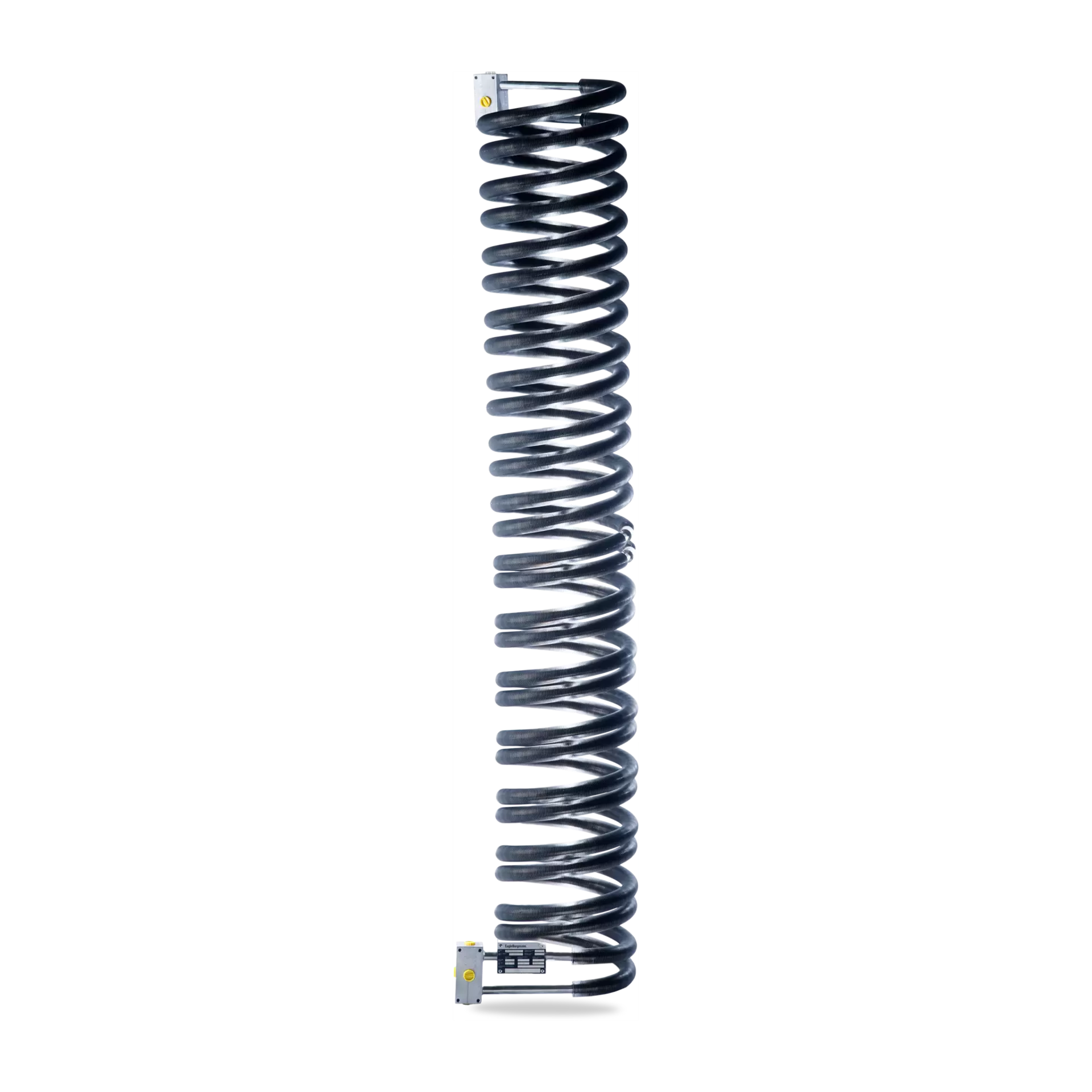
WEL2002/A003
Two finned tubes switched on parallel and double length.
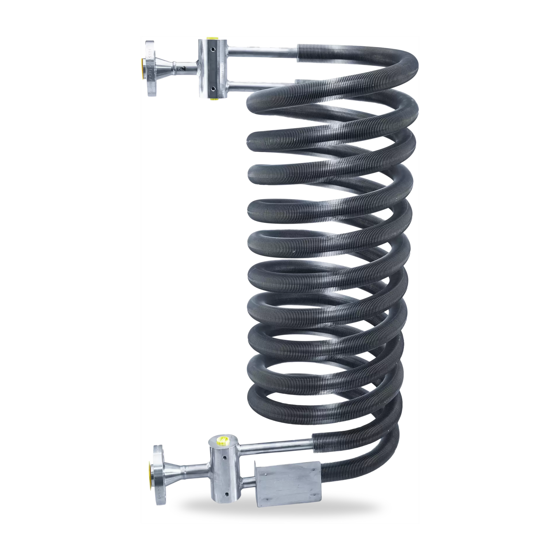
WEL6020A4A001-D0
Cooler according to API 682 4th edition.