


Click image to enlarge
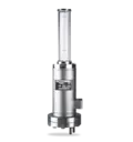
| A | Barrier medium IN (G1/2")connection possible for SPI2063 |
|---|---|
| B | Barrier medium OUT (G1/2") |
| C | Process medium (G1/2") |
| D | Coolant IN (tube 15 x 1.5) |
| E | Coolant OUT (tube 15 x 1.5) |
| F | Connection for SPN (G1/8") |
DRU2000
Features
With the EagleBurgmann DRU system it is possible to supply barrier fluid to double and tandem mechanical seals for a broad range of applications. The maximum operating pressure of 63 bar applies to the housing of the pressure booster, i.e. the process/medium pressure at the connection must be lower and is conditional on the transmission ratio:
DRU2063/A001 up to 57 bar
DRU2063/A002 up to 42 bar
Circulation in accordance with API 682 / ISO 21049: Plan 53C
Advantages
- Automatic setting of the barrier pressure via reference pressure: simple and reliable mode of operation
- Safe operation even in case of pressure changes
- Barrier pressure is created without any need for connection to a nitrogen supply
- Housing is easy to dismantle: all parts are readily accessible for cleaning
- Protective pipe for piston rod made of borosilicate glass: optimum level monitoring
Standards and approvals
- PED 2014/68/EU (Design and production in accordance with EU Pressure Equipment Directive)
- ASME VIII, Div. 1 (Design, calculation and production)
Recommended applications
- Refining technology
- Oil and gas industry
- Chemical industry
- Petrochemical industry
Functional description
The function of the DRU system is similar in principle to the TS system. The difference is that the barrier pressure is created by the reference pressure without any additional superimposition of nitrogen. The pressure booster is for storing and cooling the barrier fluid. Pressurization is by means of a piston in dependency on the process/medium pressure. Automatic pressure increase in accordance with the transmission ratio.
Product variants
| Designation | DRU2063/A001 | DRU2063/A002 | DRU2063/A101 | DRU2063/A102 |
|---|---|---|---|---|
| Design code | PED 2014/68/EU | PED 2014/68/EU | ASME VIII, Div. 1 | ASME VIII, Div. 1 |
| Integrated cooling coil | ■ | ■ | ■ | ■ |
| Transmission ratio | 1:1.1 | 1:1.5 | 1:1.1 | 1:1.5 |
| Volume, jacket (liters) | 4 | 4 | 4 | 4 |
| Volume, cooling coil (liters) | 0.7 | 0.7 | 0.7 | 0.7 |
| Allowable pressure1) | 63 bar(913 PSI) | 63 bar(913 PSI) | 63 bar(913 PSI) | 63 bar(913 PSI) |
| Allowable process/mediumpressure at connections C1) | 57 bar(827 PSI) | 42 bar(609 PSI) | 57 bar(827 PSI) | 42 bar(609 PSI) |
| Allowable working temperature1) | -60 °C ... +200 °C(-76 °F ... +392 °F) | -60 °C ... +200 °C(-76 °F ... +392 °F) | -60 °C ... +200 °C(-76 °F ... +392 °F) | -60 °C ... +200 °C(-76 °F ... +392 °F) |
| Working volume, MAX-MIN (liters) | 2 | 1.5 | 2 | 1.5 |
| Cooling capacity –without cooling water (kW) 2) | 0.5 | 0.5 | 0.5 | 0.5 |
| Cooling capacity –natural circulation (kW)2) | 1.5 | 1.5 | 1.5 | 1.5 |
| Cooling capacity –forced circulation (kW)2) | 4 | 4 | 4 | 4 |
| Metal parts | 1.4571 | 1.4571 | 1.4571 | 1.4571 |
| Protective tube for piston rod | Borosilicate | Borosilicate | Borosilicate | Borosilicate |
| Seal | PTFE | PTFE | PTFE | PTFE |
| Net weight (approx.) | 51 kg(112 lb) | 51 kg(112 lb) | 51 kg(112 lb) | 51 kg(112 lb) |
Other versions on request.
1) Design data, permissible working values depend on the actual conditions of service.
2) The cooling performance depends on the available fluids, their temperatures and flow rates. Please contact EagleBurgmann for professionally selecting the correct heat exchanger.
