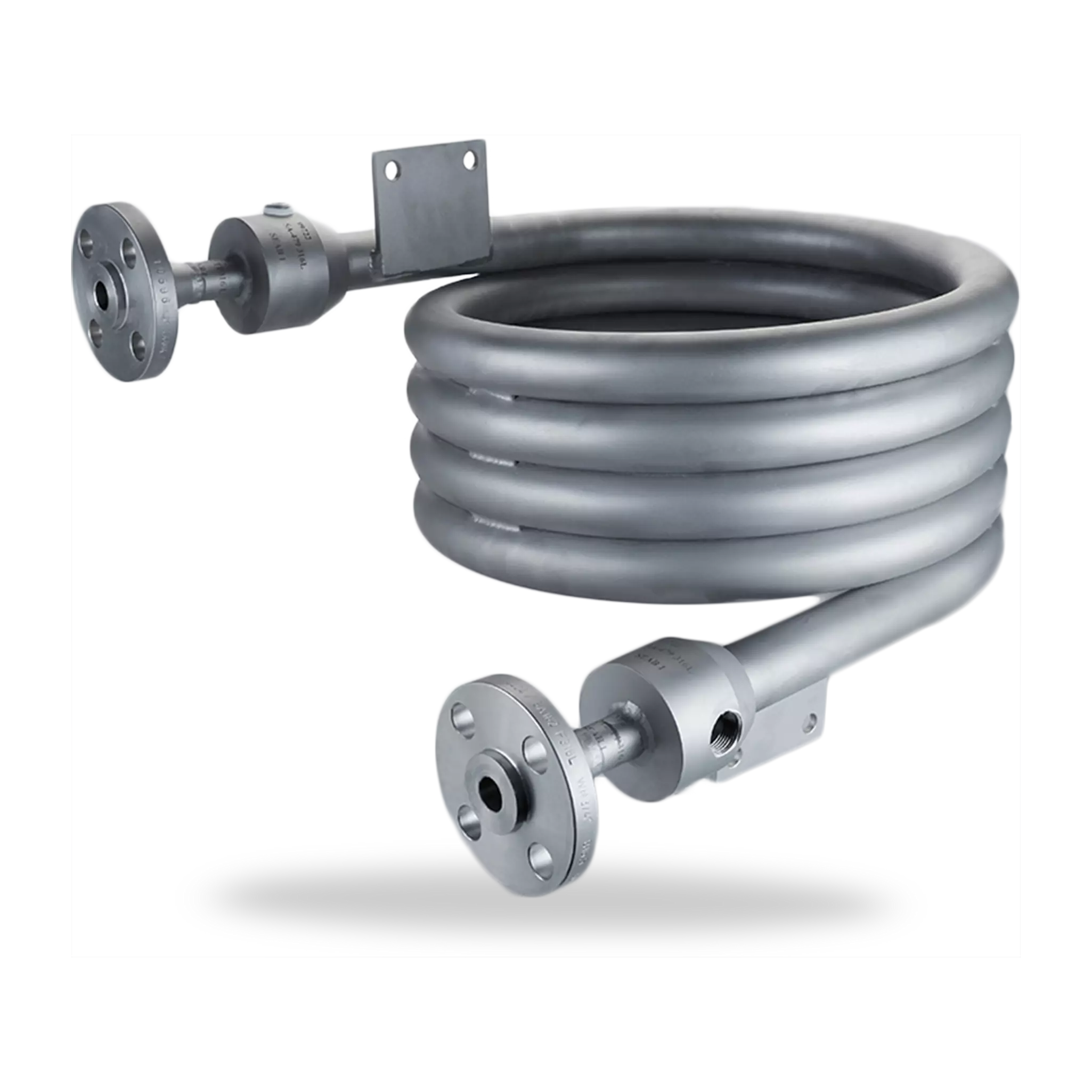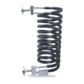


Click image to enlarge
WEL6002A4
A From mechanical seal
B To mechanical seal
C Vent
D Drain
WEL6
Air cooler
Features
Heat exchangers of the WEL6000A4 range (shown here: WEL6002A4) are used to cool process/barrier fluids in seal supply circuits. The heat exchangers are made of helical, laser-welded finned tubes. The cooling medium is ambient air. It is important, therefore, for WEL heat exchangers to be installed in well ventilated places indoors or, ideally, outdoors. There is a choice of three different basic versions of the WEL6 range as well as being supplied fully assembled together with valves, base frame and other system components.
Advantages
- Operating limits up to 44 bar / 260 °C
(638 PSI / 500 °F) (tube side): suitable for a wide range of demanding operating conditions. - Can be completely vented and drained
- Seamless pipes
- Stainless steel 316/316L: high resistance to corrosive media
Standards and approvals
- API 682 / ISO 21049
- API 682 4th ed. Cat. 2/3 - 1CW-FL
- API 682 4th ed. Cat. 2/3 - 2CW-CW
- API 682 4th ed. Cat. 2/3 - 2CW-CS
- API 682 4th ed. Cat. 2/3 - 3CW-FB
- API 682 4th ed. Cat. 2/3 - 3CW-BB
- API 682 4th ed. Cat. 2/3 - 3CW-FF
- API 682 4th ed. Cat. 1 - 1CW-FX
- API 682 4th ed. Cat. 1 - 2CW-CW
- API 682 4th ed. Cat. 1 - 3CW-FB
Recommended applications
- Refining technology
- Oil and gas industry
- Petrochemical industry
- Chemical industry
- Power plant technology
Notes
PED 2014/68/EU (Design and production in accordance with EU Pressure Equipment Directive) or ASME VIII, Div. 1 (Calculation based on ASME VIII, Div. 1 - cooler not subject to ASME stamp requirements, piping <6")
Product variants
| Designation | WEL6001A4A001-D0 | WEL6002A4A001-D0 | WEL6004A4A001-D0 |
|---|---|---|---|
| Type of heat exchanger | ASME | PED | ASME |
| Number of finned tubes | 1 | 2 finned tubes switchedin parallel | 2 finned tubes switchedin parallel and doubled length |
| Connections | Flange 3/4", 600 lbs | Flange 3/4", 600 lbs | Flange 3/4", 600 lbs |
| Drain / vent connection | Flange 1/2", 600 lbs 4) | Flange 1/2", 600 lbs 4) | Flange 1/2", 600 lbs 4) |
| Allowable pressure1) | 44 bar(638 PSI) | 44 bar(638 PSI) | 44 bar(638 PSI) |
| Allowable temperatureprocess/barrier mediumside (tube side) 1) | -29 °C … +260 °C(-20 °F … +500 °F) | -29 °C … +260 °C(-20 °F … +500 °F) | -29 °C … +260 °C(-20 °F … +500 °F) |
| Cooling capacity (kW)2) | 1.5 | 2 | 3 |
| Cooling capacity (kW)3) | 0.9 | 1.4 | 1.8 |
| Volume (liters) | 0.7 | 1.1 | 1.5 |
| Metal parts | 316/316L | 316/316L | 316/316L |
Other versions on request.
1) Design data, permissible working values depend on the actual conditions of service.
2) Guidelines with barrier/buffer fluid water 60 °C (140 °F) – ambient temperature 20 °C (68 °F);
moved air at min. 0.7 m/s (2.3 ft/s); product flow rate 8 l/min.
3) Guidelines with barrier/buffer fluid oil 60 °C (140 °F) – ambient temperature 20 °C (68 °F);
moved air at min. 0.7 m/s (2.3 ft/s); product flow rate 8 l/min.
4) Version with screwed connection G1/2" available as an option.