

Click image to enlarge
WEF6000A4
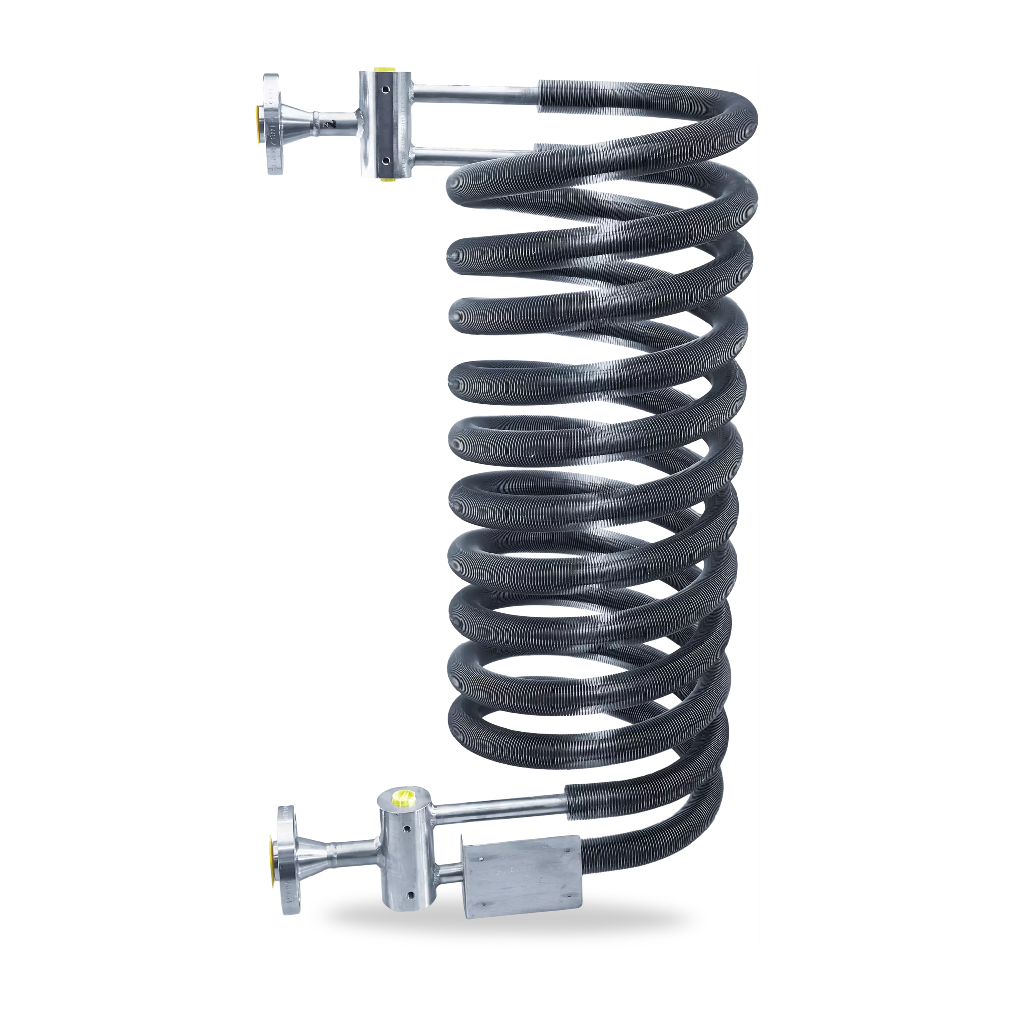
A From mechanical seal
B To mechanical seal
C Cooling water IN
D Cooling water OUT
E Vent
F Drain
WEF6 Water cooler
Features
Heat exchangers of the WEF6 range are used to cool process/barrier fluids in seal supply circuits. WEF6 heat exchangers are fully compliant with API 682 4th edition regulations. The process/barrier medium is directed through the tube, and the cooling medium is directed through the shell.
Venting and draining of the process/barrier medium side as well as the cooling water side is ensured. In addition, the heat exchangers can also be combined with a temperature instrument in the supply line to the mechanical seal (optional in accordance with API 682 4th edition).
Advantages
- Operating limits up to 65 bar / 260 °C
(943 PSI / 500 °F) (tube side):
suitable for a wide range of operations - Cooling water and process side can be completely vented and drained
- Seamless pipes on process side
- Special design without welding inside the cooler
- Higher cooling water velocity due to innovative cooler design
- Stainless steel 316/316L: high resistance to corrosive media
Standards and approvals
- PED 2014/68/EU (Design and production in accordance with EU Pressure Equipment Directive)
- ASME VIII, Div. 1 possible (see notes)
- API 682 4th edition
Recommended applications
- Refining technology
- Oil and gas industry
- Petrochemical industry
- Chemical industry
- Power plant technology
Notes
Design and production in accordance with EU Pressure Equipment Directive PED 2014/68/EU.
Design, calculation and production acc. to ASME VIII, Div. 1
(cooler not subject to ASME stamp requirements, piping <6")
Cleaning:
Process/barrier medium side and cooling water side: flush with a suitable solvent.
Product variants
| Designation | WEF6100A4 | WEF6101A4 | WEF6000A4 | WEF6001A4 |
|---|---|---|---|---|
| Design code | ASME VIII, Div. 1 | PED 2014/68/EU | ASME VIII, Div. 1 | PED 2014/68/EU |
| Tube | Shell | Tube | Shell | |
| Process connections | Flange 3/4",600 lbs | NPT 3/4" | Flange 3/4",600 lbs | NPT 3/4" |
| Drain / vent connection | NPT 1/2" | NPT 1/2" | NPT 1/2" | NPT 1/2" |
| Allowable pressure1) | 65 bar(943 PSI) | 25 bar(362 PSI) | 65 bar(943 PSI) | 25 bar(362 PSI) |
| Allowable temperaturecooling water side (shell side)1) | -29 °C … +150 °C(-20 °F … +302 °F) | -29 °C … +150 °C(-20 °F … +302 °F) | -29 °C … +150 °C(-20 °F … +302 °F) | -29 °C … +150 °C(-20 °F … +302 °F) |
| Allowable temperatureprocess/barrier medium side (tube side)1) | -29 °C … +260 °C(-20 °F … +500 °F) | -29 °C … +260 °C(-20 °F … +500 °F) | -29 °C … +260 °C(-20 °F … +500 °F) | -29 °C … +260 °C(-20 °F … +500 °F) |
| Cooling capacity (kW)2) | 10 | 10 | 10 | 10 |
| Metal parts | 316/316L | 316/316L | 316/316L | 316/316L |
Other versions on request.
1) Standard design data, extendend pressure / temperature rating on request.
2) The cooling performance depends on the available fluids, their temperatures and flow rates. Please contact EagleBurgmann for professionally selecting the correct heat exchanger.