

Click image to enlarge
| Item | Description |
|---|---|
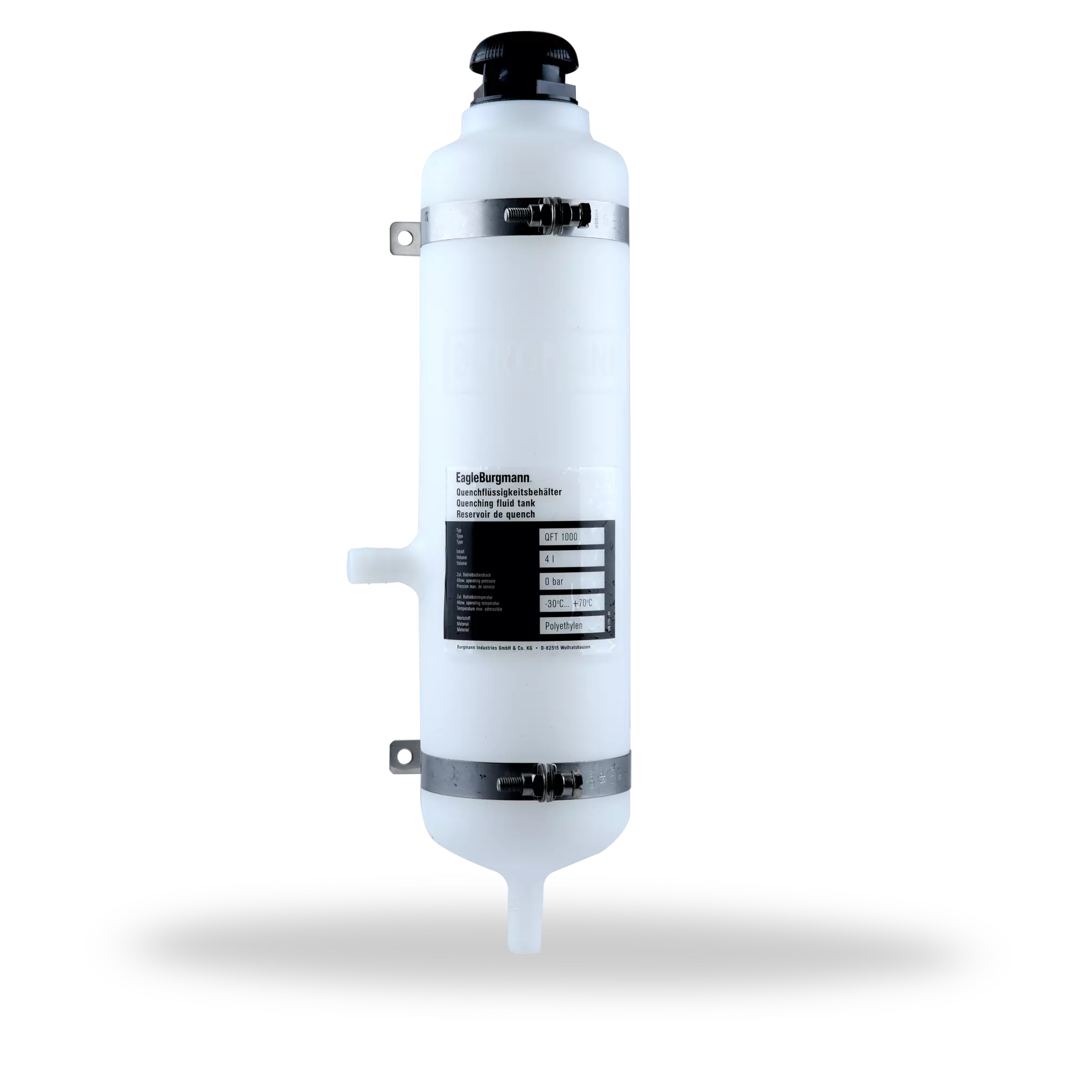
| 1 | Storage tank (capacity 3 l) |
| 2 | Inlet filter with vented cap |
| 3 | Sight-glass or level switch |
| 4 | Name plate |
| 5 | Overflow G 1/8 |
Connections
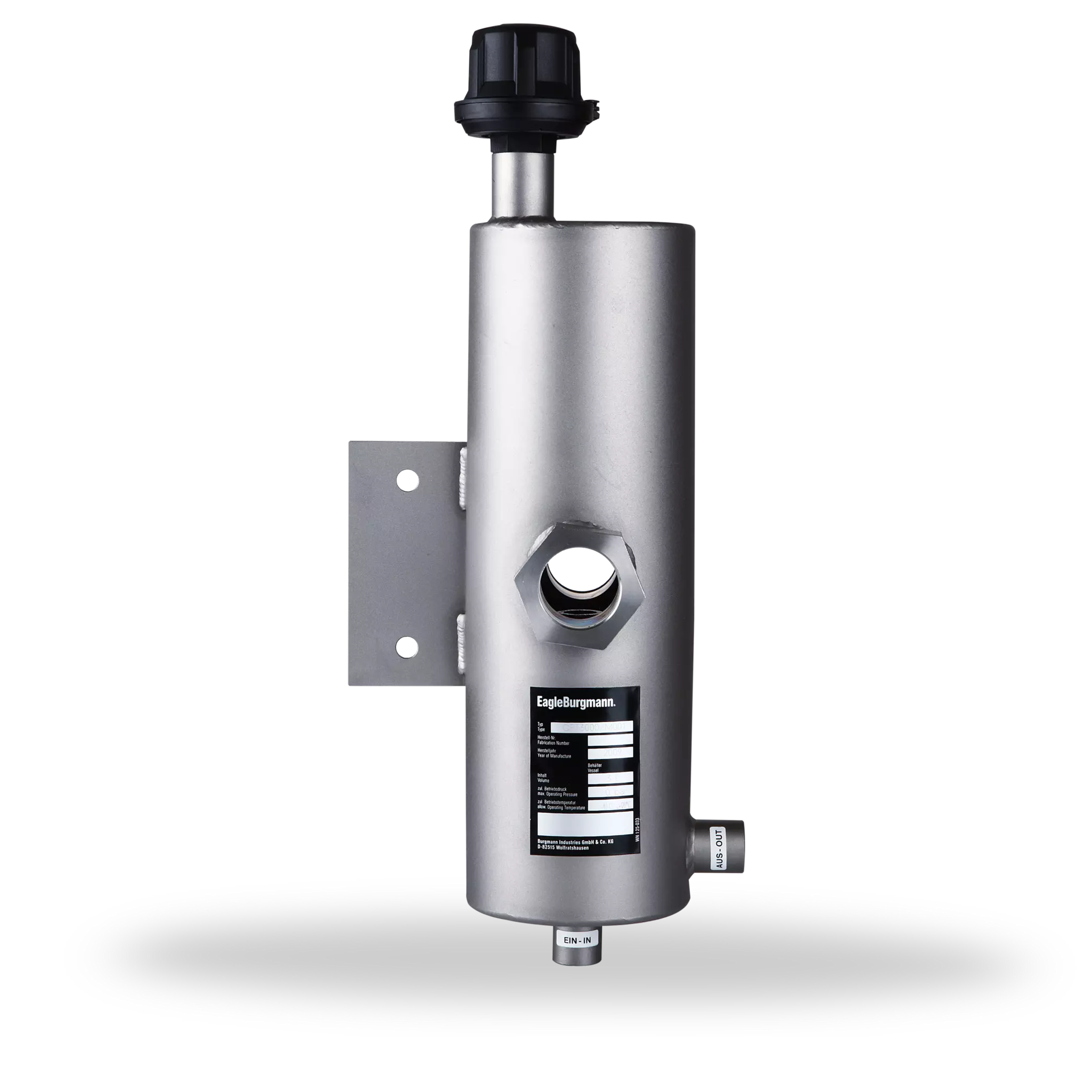
| A | To the mechanical seal |
|---|---|
| B | From the mechanical seal |
| C | Filling |
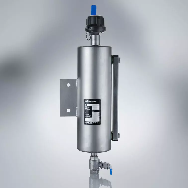
QFT2000
Features
- Available in a range of different material combinations: suitable for a wide range of demanding operating conditions
- Design for medium temperatures of up to +200 °C (+392 °F)
- Tank made of 1.4571: high resistance to corrosive media
- Integrated overflow for selective discharge of leakage
- Instead of the sight-glass it is possible to use a level switch to monitor the fluid volume
- Combined filling and ventilation filter in the quench fluid tank for reliable operation
Advantages
Quench fluid supply systems are used to supply single or tandem mechanical seals. They act as a convenient fluid reservoir. The exchange of fluid takes place by the thermosiphon principle or by forced circulation, e.g. with a pumping screw. The QFT2000 stainless steel tank is equipped with sight-glasses for monitoring the MIN/MAX level and can be fastened with a lug fixture. The leakage overflow can be selectively discharged.
Supply of mechanical seal based on API 682 / ISO 21049, Plan 51.
Recommended applications
- Chemical industry
- Food and beverage industry
- Pharmaceutical industry
Functional description
Quench fluid systems are employed:
- to absorb leakage
- to monitor the leakage rate (e.g. through periodic reading of the level in the tank)
- to lubricate and to cool the outboard mechanical seal in a tandem arrangement
- to prevent icing
- to protect against dry running
- to stabilize the lubricating film
- to exclude air from the media in order to prevent a reaction with oxygen in the air
Notes
Install the quench fluid tank approx. 1 ... 2 m (3.3 ... 6.6 ft) above the mechanical seal. Install connection pipes to the mechanical seal with low flow resistance. Pipes must vent automatically in the direction of the tank. It is imperative that air pockets are prevented. The minimum filling level must always be above the connection socket at the side (in the case of the thermosiphon principle).
Quench fluid systems can be operated in two different modes.
Product variants
| Description | QFT2000-00 | QFT2000/A001 | QFT2000/A002 | QFT2000/A500 | QFT2000/A501 | QFT2000/A502 |
|---|---|---|---|---|---|---|
| Standard design | ■ | ■ | ||||
| Volume (liters) | 3 | 3 | 3 | 3 | 3 | 3 |
| Allowable pressure | Pressureless | Pressureless | Pressureless | Pressureless | Pressureless | Pressureless |
| Allowable temperature | -30 °C ... +70 °C(-22 °F ... +158 °F) | -30 °C ... +120 °C(-22 °F ... +248 °F) | -30 °C ... +200 °C(-22 °F ... +392 °F) | -30 °C ... +70 °C(-22 °F ... +158 °F) | -30 °C ... +120 °C(-22 °F ... +248 °F) | -30 °C ... +200 °C(-22 °F ... +392 °F) |
| Material, tank | ||||||
| 1.4571 | ■ | ■ | ■ | ■ | ■ | ■ |
| Material, filling filter | ||||||
| Polyamide | ■ | ■ | ■ | ■ | ||
| 1.4571 | ■ | ■ | ||||
| Material, inspection glass | ||||||
| Acrylic/NBR | ■ | ■ | ||||
| Borosilicate/PTFE | ■ | ■ | ■ | ■ | ||
| Process connections | ||||||
| G 1/2" | ■ | ■ | ■ | |||
| 1/2 NPT | ■ | ■ | ■ |
Instead of the inspection glass, a level switch can be used for monitoring the fluid volume:
MIN level: SPS2000/A051-00
MAX level: SPS2000/A052-00
MIN/MAX level: SPS2000/A053-00