

Click image to enlarge
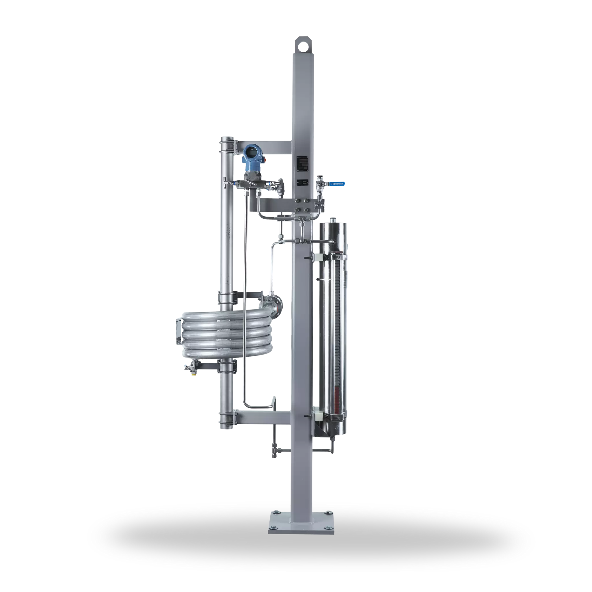
SPB6002A4 with air cooler
A From mechanical seal
B To mechanical seal
C Fill
F Drain
H N2 Precharge
SPB (Plan 53B)
Features
Pressurized barrier system (closed circuit) for use in seal systems with high pressures and/or for hazardous/environmentally harmful processes. The SPB (Plan 53B) range is available with a pressure accumulator, cooler (finned tube, water or air cooler with fan) and a wide range of instruments.
Circulation in accordance with API 682 / ISO 21049: Plan 53B
Advantages
- Pressurization is by means of a pre-loaded bladder accumulator
- The nitrogen is separated from the barrier medium by membranes in the accumulator: nitrogen cannot get into the barrier medium or process medium
- Barrier pressure is created without any need for connection to a nitrogen supply
- Available with finned tube, water or air coolers with fan
- Modular system: combination with a wide range of system components/instruments possible
Standards and approvals
- PED 2014/68/EU (Design and production in accordance with EU Pressure Equipment Directive)
- ASME VIII, Div. 1 (Design, calculation and production)
Recommended applications
- Petrochemical industry
- Chemical industry
- Oil and gas industry
- Refining technology
Functional description
The SPB is designed to perform the following functions of a barrier system:
- to pressurize the barrier chamber
- leakage compensation
- to cool the seal
Pressurization (> process pressure) prevents the process medium from getting into the barrier circuit or the atmosphere. Pressurization is supplied by a pressure accumulator which is pre-loaded with nitrogen. Circulation in the barrier circuit takes place by the thermosiphon principle or by forced circulation, e.g. with a pumping screw.
Notes
A refilling unit has to be provided.
Product variants
| Designation | SPB6M0003-00 | SPB6M0004-00 | SPB6M0024-00 | SPB6M0029-00 | SPB6M0030-00 | SPB6M0031-00 |
|---|---|---|---|---|---|---|
| Design: 50barg @ 95°C(725PSI @ 203°F) | ■ | ■ | ■ | ■ | ■ | ■ |
| TubingPiping | ■ | ■ | ■ | ■ | ■ | ■ |
| air heat exchanger | WEL6 | WEL6/td> | ||||
| water heat exchanger | WEF6 | WEF6 | WEF6 | WEF6 | ||
| Cooling capacity [kW]1)/ [kW]2)Process media water | 1,4 / 1,8 | 8,2 / 12,4 | 7,1 / 10,8 | 1,4 / 1,8 | 8,2 / 12,4 | 7,1 / 10,8 |
| Cooling capacity [kW]1)/ [kW]2)Process media Oil ISO VG10 | 1,1 / 1,5 | 2,7 / 4,1 | 2,1 / 3,2 | 1,1 / 1,5 | 2,7 / 4,1 | 2,1 / 3,2 |
| Bubble memory: CrMo-StahlBubble: Nitril | 35 Liter | 35 Liter | 35 Liter | 35 Liter | 35 Liter | |
| Floating alarm | ■ | ■ | ■ | ■ | ■ | ■ |
Air cooler:
1) Low Flow: 8 l/min (Process Fluid), 0,7 m/s (Air Velocity), △T = 40K
2) High Flow: 15 l/min (Process Fluid), 1,0 m/s (Air Velocity), △T = 40K
Water cooler:
1) Low Flow: 8 l/min (Process Fluid), 10 l/min (Cooling Water), △T = 40K
2) High Flow: 15 l/min (Process Fluid), 20 l/min (Cooling Water), △T = 40K
Other versions and connections (flanged, threaded, welded) on request.
Other versions and connections (flanged, threaded, welded) on request.

SPO with a water cooler