

Click image to enlarge
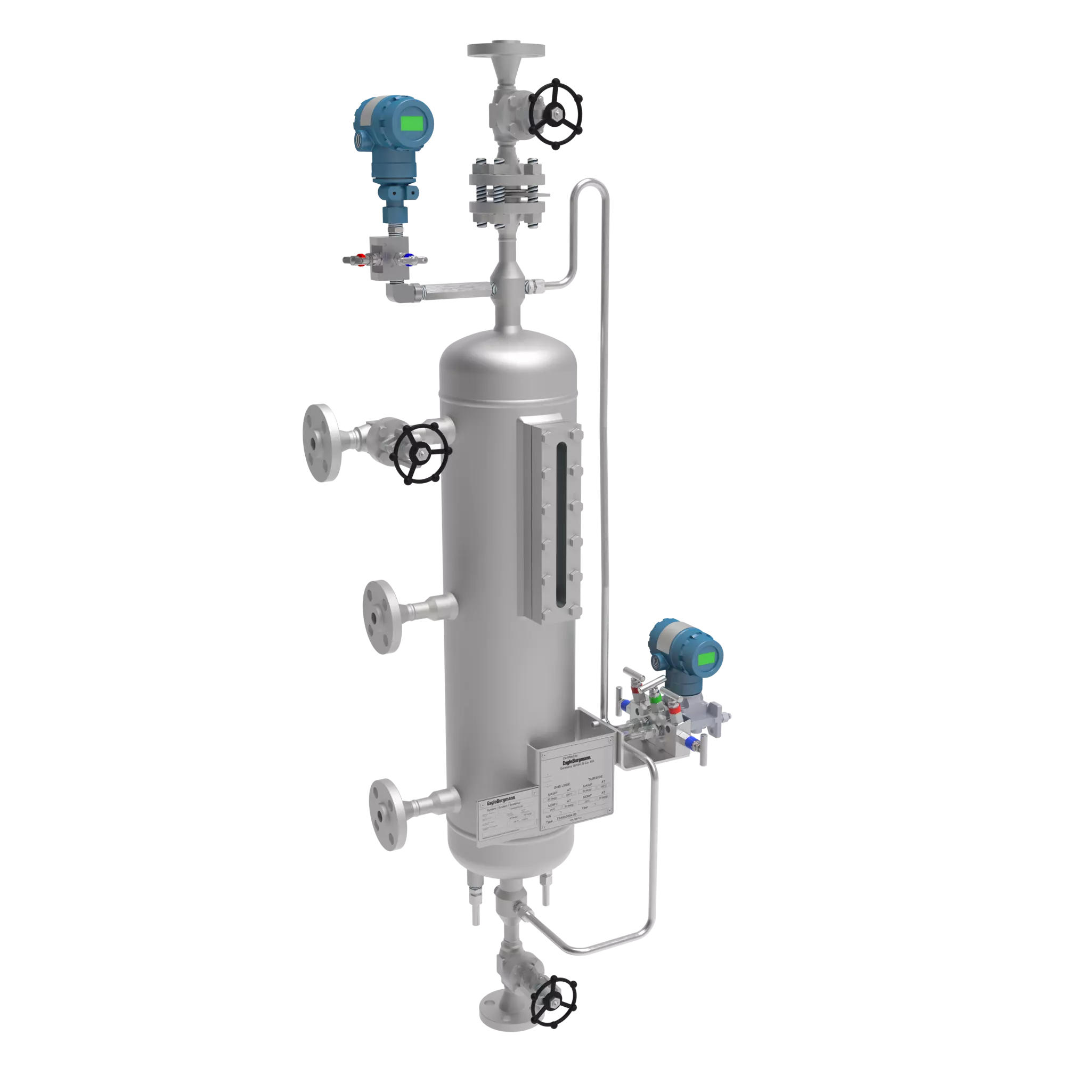
SPB6002A4
A From mechanical seal
B To mechanical seal
C Fill
F Drain
H N2 Precharge<
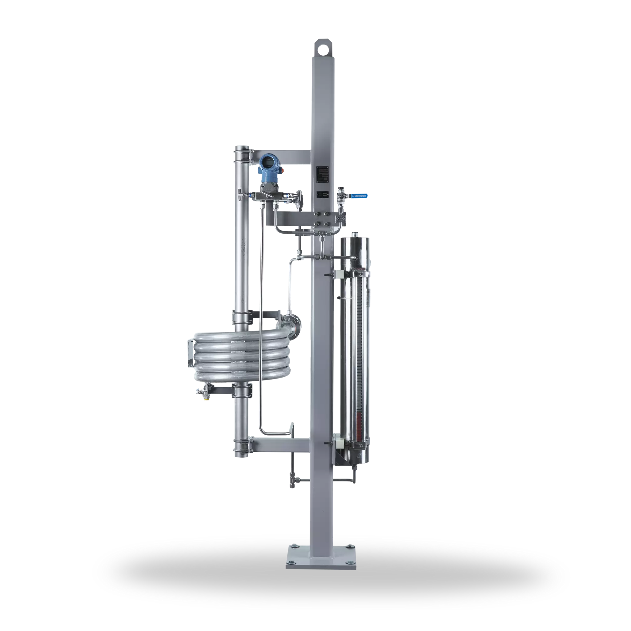
SPB6 Barrier fluid system
with bladder accumulator
Features
Pressurized barrier system (closed circuit) for use in seal systems with high pressures and/or for hazardous/environmentally harmful processes. The SPB6000A4 (Plan 53B) range is available with a pressure accumulator, cooler (finned tube, water or air cooler with fan) and a wide range of instruments.
A refilling unit has to be provided.
Advantages
- Pressurization is by means of a pre-loaded bladder accumulator
- The nitrogen is separated from the barrier medium by membranes in the accumulator: nitrogen cannot get into the barrier medium or process medium
- Barrier pressure is created without any need for connection to a nitrogen supply
- Available with finned tube, water or air coolers with fan
- Modular system: combination with a wide range of system components/instruments possible
Standards and approvals
- API 682 / ISO 21049
- API 682 4th ed. Cat. 2/3 - 3CW-FB
- API 682 4th ed. Cat. 2/3 - 3CW-BB
- API 682 4th ed. Cat. 2/3 - 3CW-FF
- API 682 4th ed. Cat. 1 - 3CW-FB
- Compliant to TA Luft (German Clean Air Act)
Recommended applications
- Refining technology
- Oil and gas industry
- Petrochemical industry
- Chemical industry
- Power plant technology
Functional description
The SPB6000A4 is designed to perform the following functions of a barrier system:
- To pressurize the buffer chamber
- As leakage compensation
- To cool the seal
Pressurization (> process pressure) prevents the process medium from getting into the barrier circuit or the atmosphere. Pressurization is supplied by a pressure accumulator which is pre-loaded with nitrogen. Circulation in the barrier circuit occurs via the thermosiphon principle or by forced circulation, e.g., with a pumping screw.
Notes
Design and production in accordance with EU Pressure Equipment Directive PED 2014/68/EU available.
Design, calculation and production acc. to ASME VIII, Div. 1 available.
3rd party inspection, ASME U-stamp on request.
Recommended piping plans
Product variants
| Designation | SPB6000A4 | SPB6001A4 | SPB6002A4 | SPB6003A4 |
|---|---|---|---|---|
| Design code | ASME VIII, Div. 1 | PED 2014/68/EU | ASME VIII, Div. 1 | PED 2014/68/EU |
| Type of cooler | Aircooler a) | Watercooler b) | Aircooler a) | Watercooler b) |
| For shaft diameters≤60 mm (acc. to API 682) | ■ | ■ | ||
| For shaft diameters>60 mm (acc. to API 682) | ■ | ■ | ||
| Bladder accumulator (liters) | 20 | 20 | 35 | 35 |
| Allowable pressure1) | 44 bar (638 PSI) | 44 bar (638 PSI) | 44 bar (638 PSI) | 44 bar (638 PSI) |
| Allowable temperature -bladder accumulator1) | -20 °C … +90 °C(-4 °F … +194 °F) | -20 °C … +90 °C(-4 °F … +194 °F) | -20 °C … +90 °C(-4 °F … +194 °F) | -20 °C … +90 °C(-4 °F … +194 °F) |
| Allowable temperature -system1) | -20 °C … +90 °C(-4 °F … +194 °F) | -20 °C … +90 °C(-4 °F … +194 °F) | -20 °C … +90 °C(-4 °F … +194 °F) | -20 °C … +90 °C(-4 °F … +194 °F) |
| Cooling capacity –with water cooled heat exchanger (kW)2) | 10 | 10 | ||
| Cooling capacity –with air cooled heat exchanger (kW)2) | 2.0 | 2.0 | ||
| Metal parts | 316/316L | 316/316L | 316/316L | 316/316L |
| Accumulator | CrMo steel | CrMo steel | CrMo steel | CrMo steel |
| Bladder | Nitrile | Nitrile | Nitrile | Nitrile |
Other versions and connections (flanged, threaded, welded) on request.
1) Design data, permissible working values depend on the actual conditions of service.
2) The cooling performance depends on the available fluids, their temperatures and flow rates. Please contact EagleBurgmann for professionally selecting the correct heat exchanger.
a) WEL6002A4
b) WEF6100A4