LNF992

Shop links for mobile

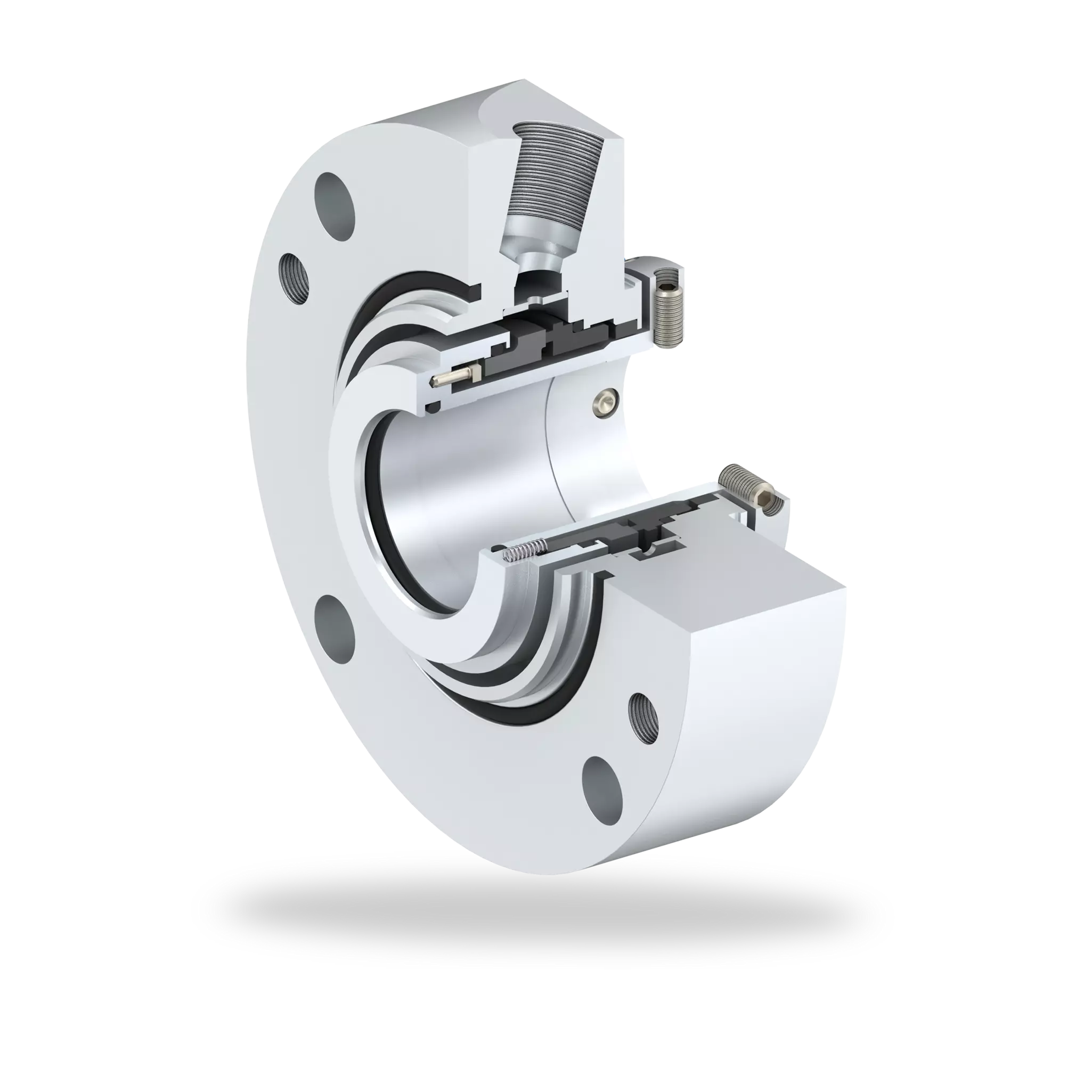
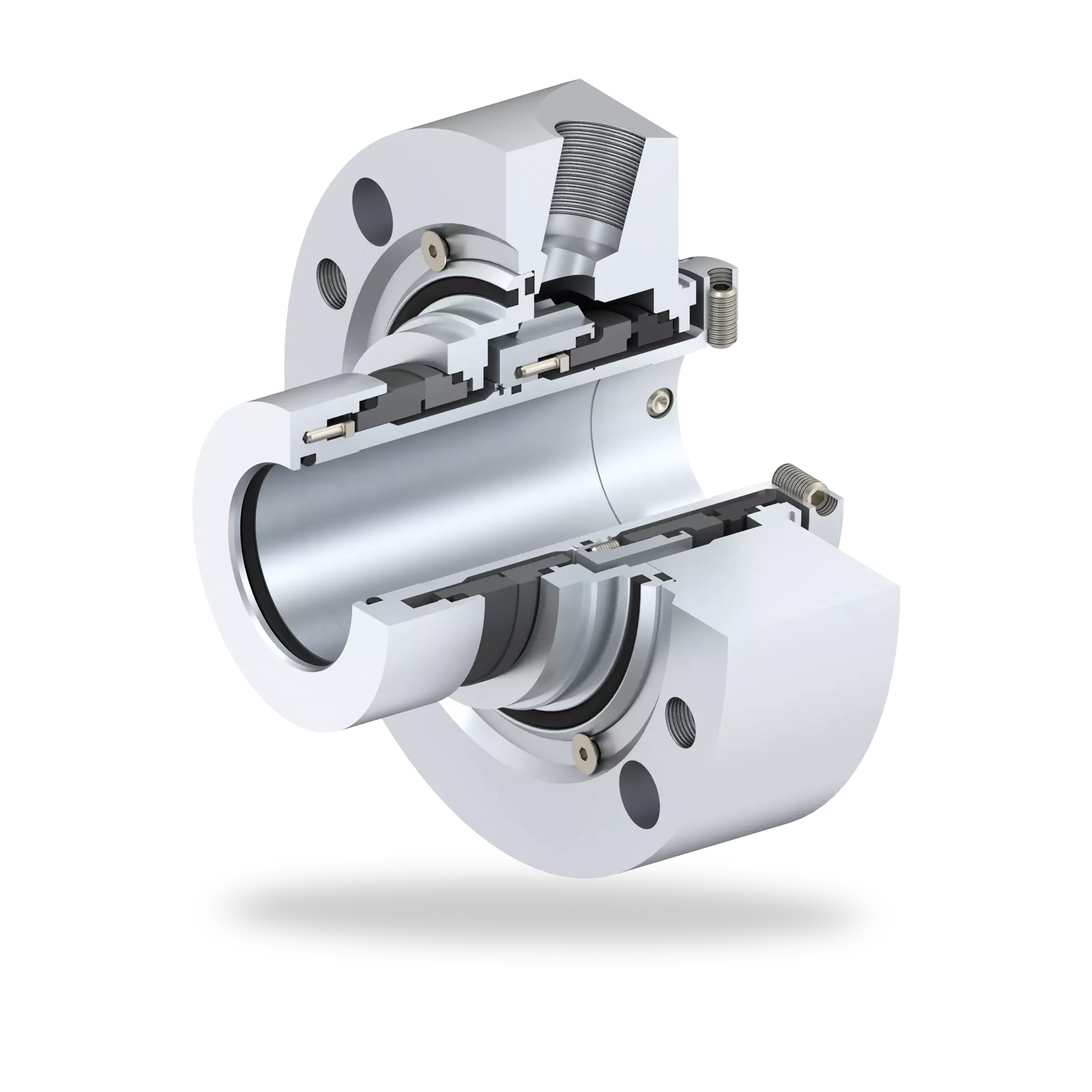
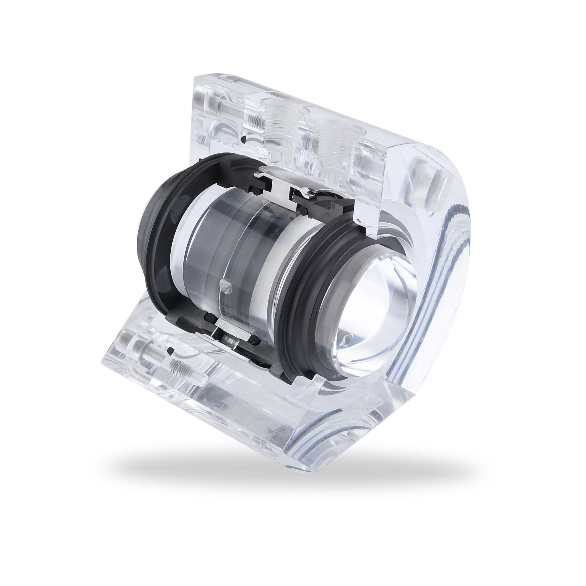
Click image to enlarge
| Item | Description |
|---|---|
| 1,8 | Seal ring |
| 2, 7, 9, 14, 16, 17, 24, 25 | O-Ring |
| 3, 10 | Thrust ring |
| 4, 11 | Spring |
| 5, 12 | Mating ring |
| 6, 13, 21, 27, 30 | Pin |
| 15 | Seal sleeve |
| 18 | Labyrinth |
| 19 | Adapter sleeve |
| 20, 26 | Gland plate |
| 22 | Adapter |
| 23 | Retaining ring |
| 28, 33 | HSH cap screw |
| 29 | Drive collar |
| 31 | Set screw |
| 32 | Setting device |
GBO Gas barrier OUT
GBI Gas barrier IN
LNF992
Features
- API 682 Category 2 and 3, Type A, Arrangement 3 seal
- Dual seal in face-to-back arrangement
- Gas-lubricated
- Balanced
- Cartridge unit
- Stationary multiple springs
- Independent of direction of rotation
- Solid seal faces
Advantages
- Non-contacting stationary spring unit design
- No process fluid penetration into the seal faces, no leakage to the atmospheric side
- Appropriate to slurry fluid
- Applicable inboard seal design for reverse and positive pressure
- Low power consumption
Operating range
Shaft diameter: d1 = 20 ... 110 mm (0.79" ... 4.33")
Pressure: p = vacuum ... 16 bar (232 PSI)
Temperature: t = -40 °C ... +160 °C (-40 °F … +320 °F)
Sliding velocity: vg = 23 m/s (75 ft/s)
Materials
Seal rings: Silicon carbide SSiC (Q1),
High density carbon graphite
Mating rings: Silicon carbide SSiC (Q1)
Secondary seals: FKM (V)
Springs: Hastelloy® C-276 (M5)
Metal parts: CrNiMo steel 316 (G)
Standards and approvals
- API 682 / ISO 21049
- API 682 4th ed. Cat. 2/3 - 3NC-FB
Recommended applications
- Gases and liquids
- Hazardous media
- Environmetal harmful media
- Monomeres
- Chemical industry
- Petrochemical industry
- Oil and gas industry
- Refining technology
- CCUS
- Alternative fuels production
- API 610 / ISO 13709 pumps
- Process pumps
Recommended piping plans
Process side:
API Plan 01
API Plan 02
API Plan 03
API Plan 11
API Plan 12
API Plan 21
API Plan 22
API Plan 31
API Plan 32
API Plan 41
Between seals:
API Plan 74