


Situation
Darlington Nuclear Generating Station with 16 Sulzer single-stage vertical reheater drain pumps
Challenge
Large temperature differences and high pressure led to inadequate cooling
Solution
SHFV1/42-E1, a new sealing system with API plan 23
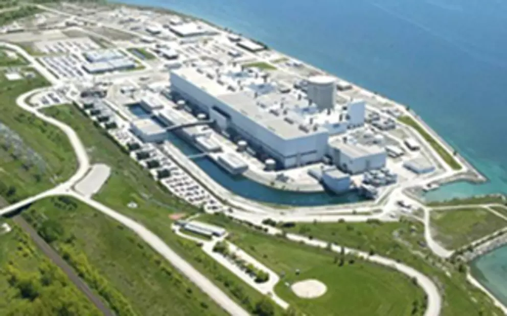
Darlington Nuclear Generating Station is located 70 km east of Toronto (Canada). The four unit station is the newest generating station of Ontario Power, performs a total output of 3,512 MW and provides about 20 % of Ontario‘s electricity needs - enough to serve a city of two million people.
16 Sulzer single-stage vertical reheater drain pumps type BJ3X4X11 model TXR are installed. The second stage reheater drains system drains the condensate, and vents any uncondensed steam from the second stage reheater tube bundles and directs these to the steam generator and the HP heater.
The pumps in question were originally equipped with a competitor‘s seal system, operated acc. to API plan 41. High temperature and high pressure caused problems for the seal and its supply system. Because of large temperature differences between the cold cooling medium (lake water) and the hot process medium (demineralized water) an excessive deposit of cooling water sediment occured and the coil of the heat exchanger regularly plugged. Therefore, inadequate cooling was provided which resulted in dry running of the seal faces and ended in seal failure.
These failures occurred up to 10 times a year and caused a loss of efficiency of 4 MW, costing 5,000 CAD per day.
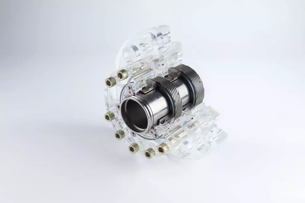
Illustr. 1: SHFV High pressure mechanical seal for boiler circulation pumps. Dual seal in tandem arrangement, with pumping screw
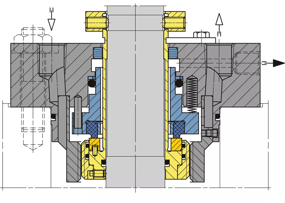
Illustr. 2: Yellow parts = rotating, blue = stationary, gray = housing
EagleBurgmann designed a new sealing system, the SHFV1/42-E1 with API plan 23. This system had to pass through a performance test at the EagleBurgmann facilities in Wolfratshausen, Germany. The test was arranged with the original equipment and under operation conditions of Darlington Nuclear. All tests have been performed successfully without any problems.
Seal features
- Stationary multiple springs and integrated pumping screw
- Pressure stabilized reinforced carbon seal face with hardened metal support ring
- Material combination for optimal heat transfer at seal faces
- Robust design prevents seal face distortion at high pressure insuring a stable lubricating film
- Safe and low leakage behavior in high speed and pressure applications
The first SHFV1/42-E1 with API plan 23 was installed in 2007. Another 15 sealing systems follwed in 2008. Since start-up the seals show excellent performance and run without any problems.
- Medium: demineralized water
- Operating temperature: 288 °C (550 °F)
- Gland injection temperature: 20 °C (68 °F)
- Stuffing box pressure: 50 bar (725 PSIG)
- Rotational speed: 3,600 min-1
- Pump type: Sulzer BJ3X4X11 model TXR
- Operation: 100 % duty pumps, 24/7 operation


